|
Back to Blog
Design Corrections4/26/2022 Upon reviewing the final design of the bridge, the team found areas that were in need of some improvements. In order to improve the speed of the overall bridge construction, the vertical members could have been included within the 3 foot and 2 foot sections of the stringers. This would have decreased the amount of bolts along with members of the bridge. Having less bridge members would allow for less time running to get the next piece during construction. Some areas along the bridge could have only used one bolt instead of two, saving even more time during construction. The stringer connections that connect the top and bottom portions of the stringers are one such example, these connections only needed one bolt, although this may have negatively impacted sway. Lastly, for the lateral bracing members, bolts were not supposed to be welded so this would have been changed. 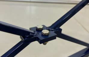 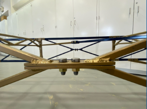 At the connections, thinner plate material could have been used to allow for the stringer template to slide across the top of the bridge easier. The thinner material would have allowed for shorter bolts to be used and a lighter overall weight. Since the 1-¾” bolts were used, the fabrication needed to be exact because the stringer template only allowed for two-inch wide stringers. The head of the bolt was 15/64” inches long so the lateral bracing had to be fabricated down to the 1/32 of an inch to insure that the stringers were 33.5 inches apart in order for the clearance to be met. This process became very time consuming, and ultimately led to less time for construction practice for the competition. This revision would have allowed for the team to be able to try alternative construction sequences or to perfect the preferred sequence even more. 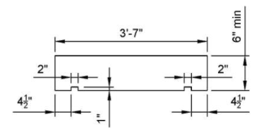
0 Comments
Back to Blog
Regional Competition4/9/2022 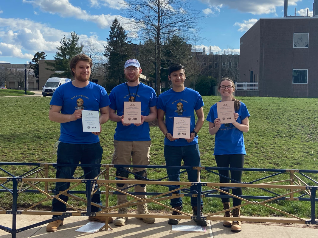 We had regional competition this weekend! TCNJ competed against 5 other teams in the Metropolitan Region. The competition was held by Rutgers University. They provided the location, food, judges and everything else needed for the regional competition. It was a full day affair. The team was able to construct the bridge in just 22 minutes and 39 seconds! There were only 6 drops in total which was very good for the total amount of bolts and nuts that had to be installed when building. The load test was completed with the bridge only deflecting 0.489 inches with only 0.025 inches being on the cantilever end. The bridge passed in sway and was a total of 263 pounds. With these results we scored second in stiffness and third in both construction time and lightness. The bridge was presented so well, being painted school colors, having a school name plate created with the waterjet machine, and with a sleek poster design, we earned first place in aesthetics! We are overall very happy with our performance and happy to have been able to participate in such an involved senior project. We all learned so much from working hard the whole academic year and having a great end result because of it.
Back to Blog
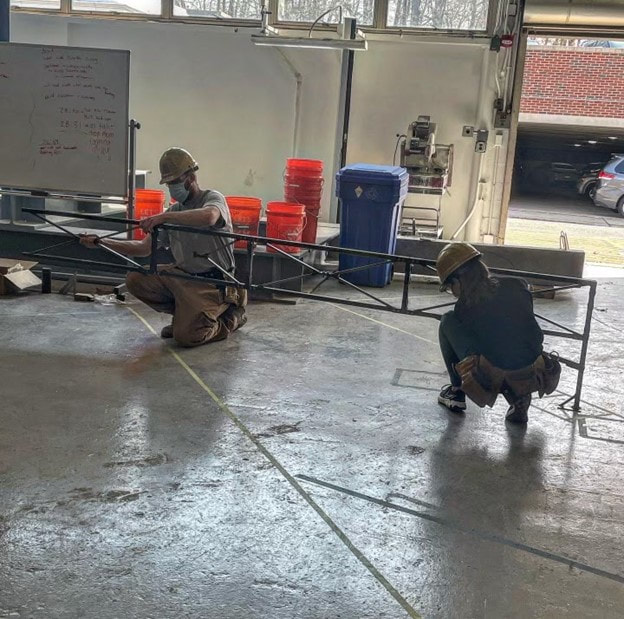
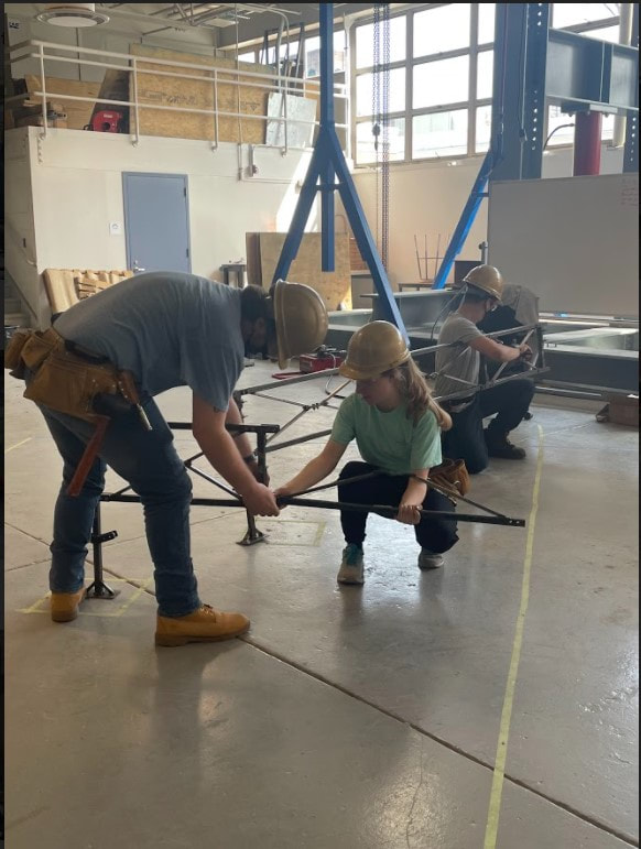
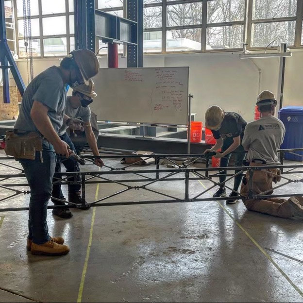
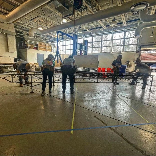
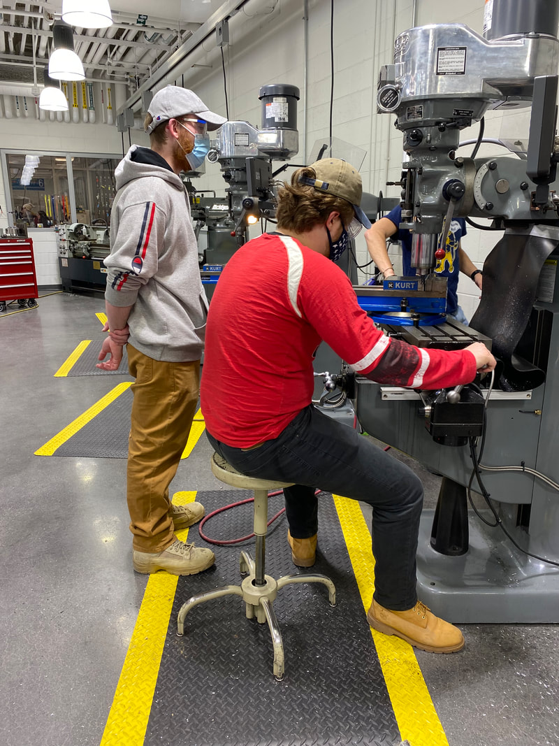
Construction Practice3/27/2022 The team was running around endlessly for the second half of March. This is no joke because let me tell you building a bridge is tiring. The team was up for the task though because we were able to get our construction time down to 23 minutes from the first time of 40 minutes. For the steel bridge competition each team is required to build their bridge as fast as they can. This construction time is calculated into the final score. For our team we are opting to have 5 builders. This allowed us to get under the 30 minute mark. After 30 minutes there is a penalty that anything over counts as 180 minutes of construction time. After the 45 minute mark the bridge construction has to be stopped. Our team had to come up with the best way to construct the bridge to cut down as much time as possible. The Construction will start with two people on the West side of the highway and three people on the East side. The West Side will build the North stringer extended to east side of the highway, simultaneously the East side will build the South stringer extended to the west side of the highway. Once the East Side has finished the south stringer portion, they will build the North stringer from the east footing to the highway. The West side North stringer will be swung across the highway for the East side to connect the stringer’s entire back span between the two North footings. The West side will then construct the South stringer to connect with the already built and tightened East side of the back span. The East side constructs the cantilever portion of the stringers, while the West side begins placing lateral bracing. The diagonal lateral bracing is then placed and then all of the stringers and bracing is fully tightened. For the next two weeks the team will continue to practice building the bridge as well as painting it to make the bridge aesthetically pleasing.
Back to Blog
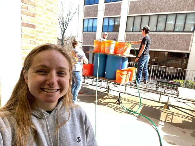
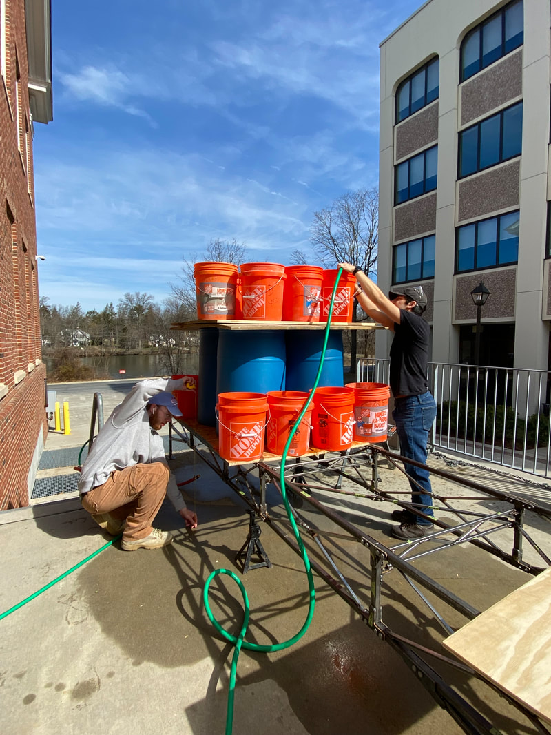
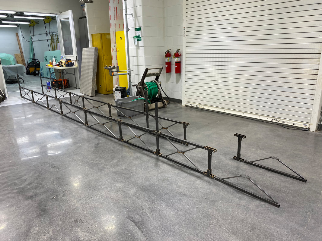
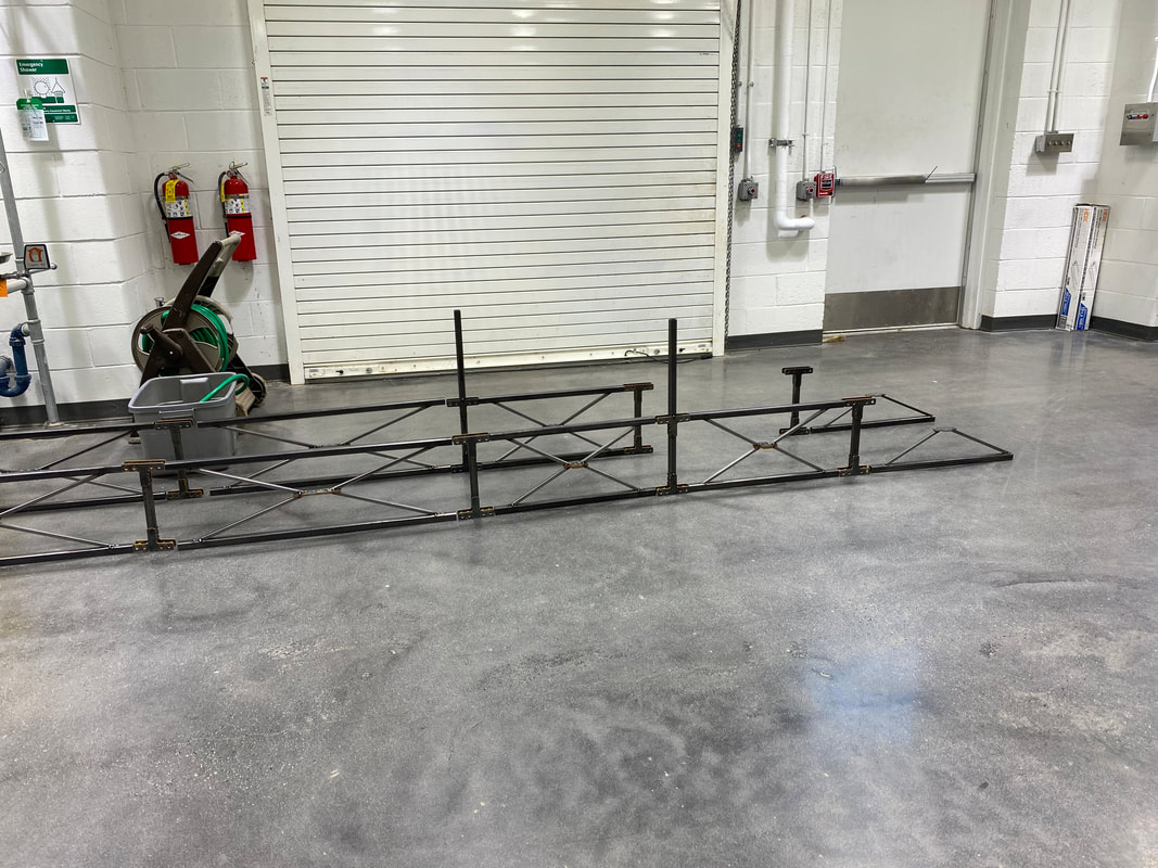
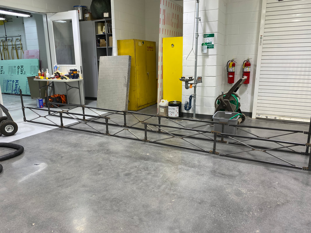
Load Testing3/15/2022 During the first half of March the finishing touches were completed. The final stages of fabrication included making the diagonal lateral bracing and welding the bolts to the angles for the lateral bracing. Clearances were also checked to make sure the bridge would pass all the measurement specifications from the guidelines. Load testing was also performed for the bridge. The two tests were for sway and deflection based on the competition guidelines. For the sway test it was recorded at two positions, the midway point on the north side back span and 1 inch from the end of the cantilever on the south side. A 50 pound pulling force was applied at both positions. The sway was recorded by utilizing a level laser and ruler. The sway was recorded to be ¼ inch for the back span and ½ inch for the cantilever, which both meet the requirement of ¾inch for the competition. For the deflection test the team loaded the bridge using 30 gallon drums and 5 gallon buckets filled with water to obtain the necessary 2500 pounds of weight that will be administered during competition. Before loading was performed, the bridge height was measured at the back span and cantilever to be 26 1/2 inch and 26 3/8 inch respectively. The bridge was then loaded based on the worst case scenario dimensions and the deflection was measured. At the center of the 3 foot load at the back span and cantilever, the height of the bridge was 26 3/8 inch and 26 inch. The difference in height is the deflection that the bridge experienced, which was found to be 1/8 inch and 3/8 inch for a total aggregate deflection of 1/2 inch. The maximum aggregate deflection allowed is 2 ½ inches. The bridge passed the deflection test with flying colors. After the loading test was completed all the drums and buckets of water were removed. The bridge was remeasured to see if there was any permanent deformation. The bridge held up very well and the only thing we had to do was bend a connection plate to make it fit within the clearance template smoothly. The load testing was a success for both sway and deflection. The next step is now practicing building the bridge for competition.
Back to Blog
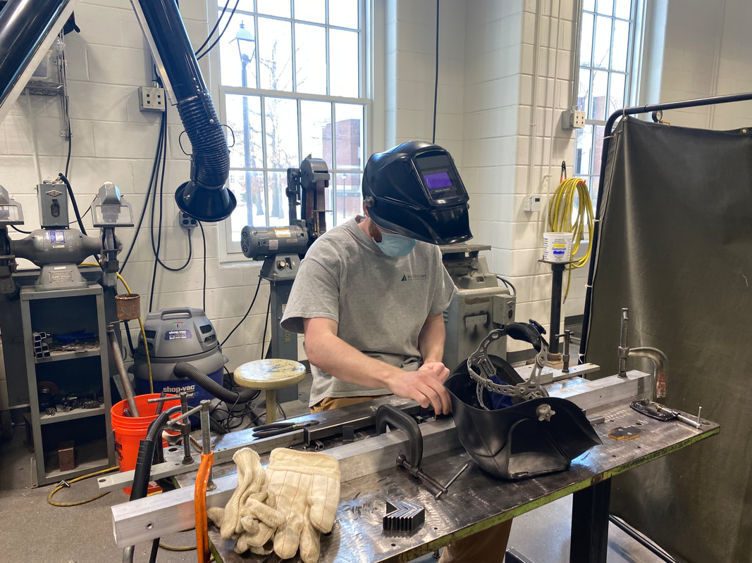
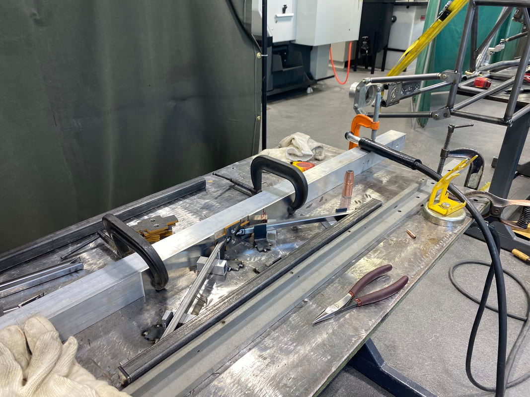
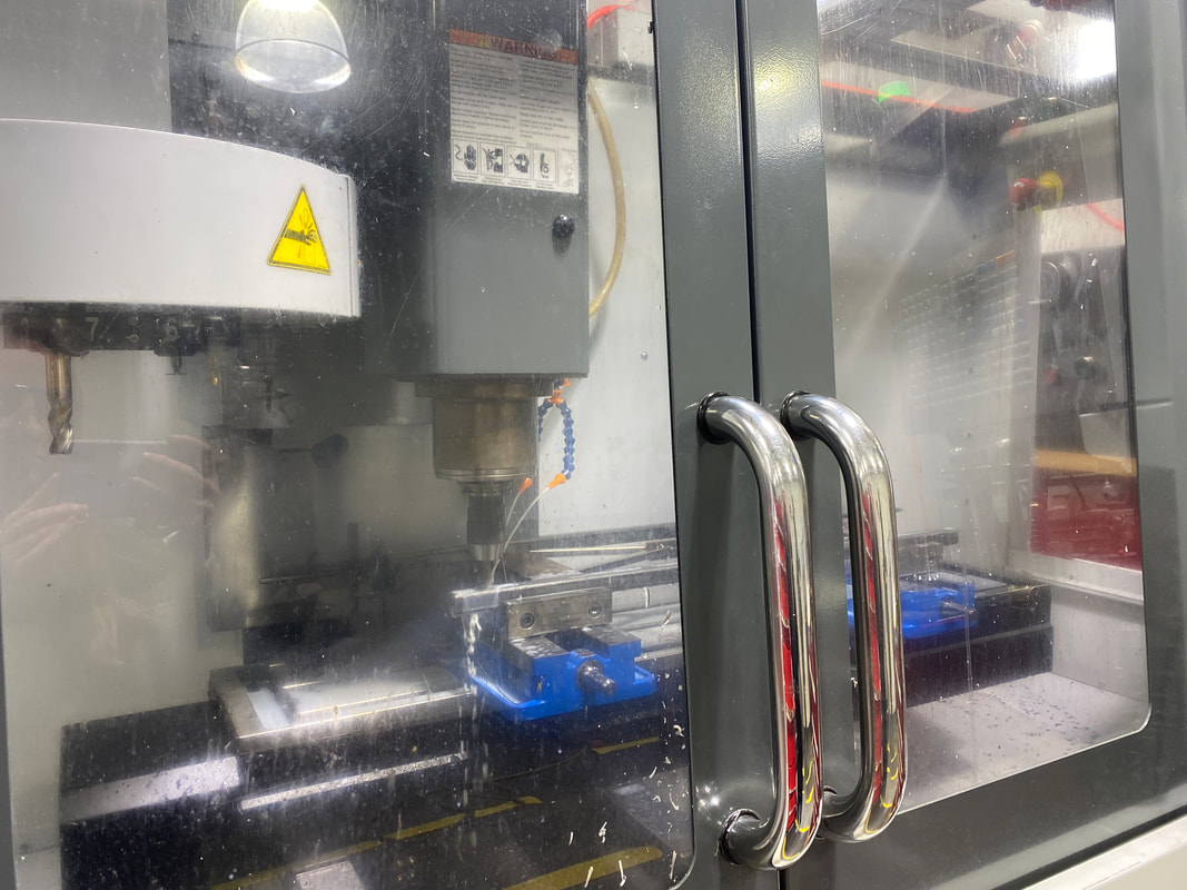
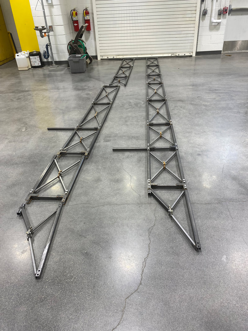
Bridge Update2/26/2022 During the second half of February the supports for the stringers were created. The lengths were cut and the angles were added. We found that there was error with the lengths because the 7.5 inch clearance was not being met. The team discussed a solution and we ended up trimming the length of the members to get the clearance instead of making smaller angles; the smaller the angles the harder to manufacture. The connection plates for these supports were cut with the waterjet machine. After all the pieces were to their correct dimensions, the supports and the footings including the stringer pieces were laid out. This made it easier for us to spot weld the plates in the correct position on the supports. All the plates for the supports were spot welded to the footings. The next big task was the lateral bracing. After a long discussion with team members and the machine shop advisor we came to our final design. This included two different types of sections; a 3 inch section for the west end and a 5 inch section for the cantilever end with four diagonals in between the horizontal members. This design had the best results for sway in visual analysis and the angles were manageable. The lateral bracings were all spot welded after a welding set up was made for each type. The lateral bracing was then cut with the band saw in order for us to connect a plate to all ends. This was decided to attach with ease to the vertical members of the stringers. The angles for the lateral bracing were all cut 1/4 inch with the milling machine and the bolt holes were drilled in them. The bridge is so close to assembly. After assembly of the whole bridge the full welds will be done and practice for competition will begin! Attached below is the engineering and fabrication drawings for this years steel bridge.
Back to Blog
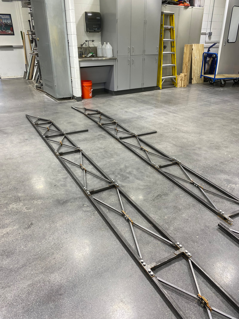
Building Progress2/15/2022 In the first couple weeks of February the stringers were spot welded. This was done by first creating a set up to hold all the pieces in place. A set up had to be created for the 2 foot and 3 foot sections. The cantilever end was designed; it had a one inch member on the bottom half and a 2 foot section on the top like the other stringer pieces. The one inch member was used for extra support. A connection plate was designed for this one inch member. The connected plate was water jetted and the piece was spot welded together. The stringers were laid out to see what parts still had to be done and to get an idea of how long the bridge would be. After all the stringer's top and bottom sections were spot welded the bolt holes had to be drilled. This was done with one of the machines with both top and bottom members connected. It allowed for precision and accuracy of the holes. This was set up for each section accordingly. After the bolt holes were drilled the holes were beveled and the members were checked to make sure they lined up with the vertical member's bolt holes. The stringers were then connected together to see if all parts fit together. Some of the plates were bent so they were corrected to fit with ease. We learned that the vertical members would have to be bolted together first and then the middle connections would be tightened after. The stringers appear to be strong and our advisors are excited to see the final product.
Back to Blog
January Fabrication Progress1/26/2022 Throughout the month of January the steel bridge was being fabricated. It began by cutting all the 2 foot and 3 foot members for the top and bottom of the stringers. The vertical pieces were cut for the stringers as well. All these members were cute 1/8" longer than specified in the plans. 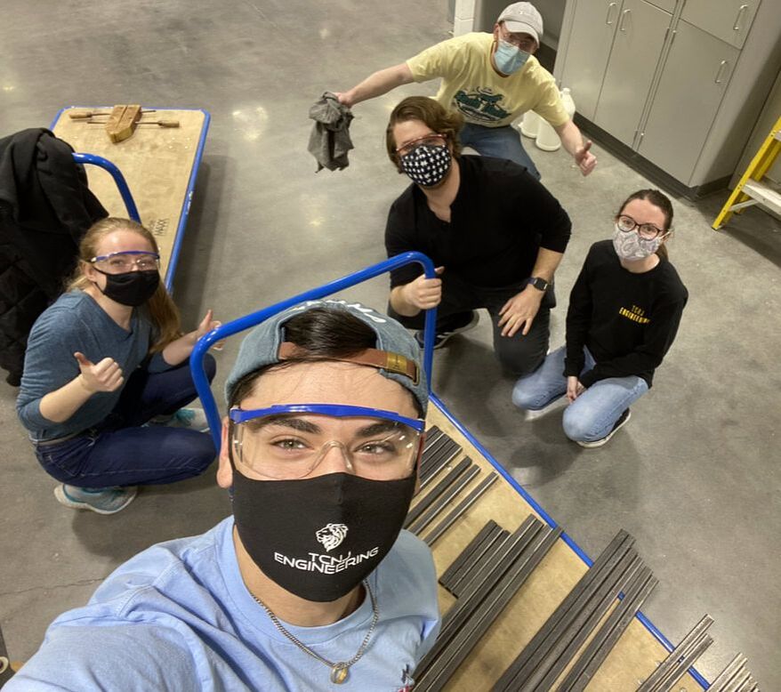 The X pieces in the middle of the stringers were cut to size and then their angles were cut at 30 or 20 degrees depending on the 2 foot or 3 foot section.   The vertical and horizontal stringer members were cut to their exact length.  The x-connection plates and horizontal stringer connection plates were cut with the waterjet machine.   The vertical member connection T-plates were spot welded to the vertical members for the stringers. 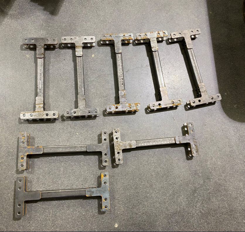
Back to Blog
Connection Designs11/22/2021 The Team met with Professional Services Specialist, Mr. Joseph Zanetti, at the TCNJ machine shop to discuss the ideas and materials for the connections of the bridge. Three types of connections were discussed and designed. The first type of connection will be utilized to connected the stringer members. These connections are attached to the vertical members in the shape of an I. Two bolts are featured on both sides of the flange that connect the vertical member to the stringer members. This connection will have a total of 8 bolts. The second type of connection is for the stringer cross bracing. This will be located at the contact point between the top and bottom parts of the stringer. This connection will have a total of 2 bolts that feed through 2 gusset plates vertically. The third connection type is a simple L bracket used for the lateral bracing. This will have a welded bolt already in place for ease of assembly. The members will be slid on through the top and fastened with a nut. All connections are made of A36 Steel gusset plates and high strength grade 8 bolts.
Back to Blog
Bridge Design Alterations11/18/2021 After meeting multiple times with the faculty advisor, industry advisor, and machine shop foreman, the team made revisions to the original final design to make it easier to assemble, easier to construct, and better performance. The first change that was made was to the stringer members. Originally, it featured 2 foot uniform members throughout the whole stringer. In the new and improved bridge, eight 3 foot members were placed where possible to reduce the number of connections and members. All except two members now feature a 2 inch offset for the cross bars, which was done for ease of connection. The 2 members that connect to the westernmost footings still feature crossbars that are flush with the edge of the member for stability purposes. Lateral supports were also altered to improve the bridge's resistance to sway. Three 32 inch by 3 inch lateral support members are featured between the footings while three 32 inch by 5 inch lateral support members are placed in the cantilevered end. The bridge also features three X shaped lateral supports. The bridge now consists of 69 total members, 85 connections, and weighs around 284 lbs. While this bridge is considerably heavier than the previous design, the team feels that these changes will overall improve the bridge's performance at competition. 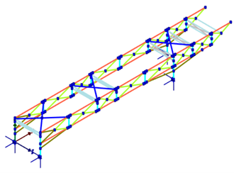
Back to Blog
Final Bridge Design10/25/2021 Upon reviewing the alternative designs put forth by each member, it was determined that Alternative Design 1 had the best score on the decision matrix and would therefore be used as the basis for our final design. Weights were given to each design criteria based on how important the team thought they would be. 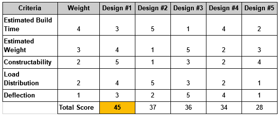 Some changes have been made to Alternative Design 1 to improve its performance. The total height of the design was increased by 2 inches, with further angled supports being added connecting to the footings. 2.5 foot lateral supports were added between stringers. The footing sizes were increased to 3in X 3in to increase stability. Thickness of members were changed to either decrease weight or decrease sway and deflection. Currently, the bridge weights an approximate 232lbs. 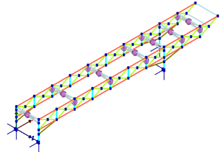
Back to Blog
Alternative Designs10/19/2021 Alternative designs were modeled using visual analysis. Five alternative truss designs were analyzed. The alternative designs had to be certain dimensions according to the competition rules. The rectangular pipe shape was assumed to be the same for all truss designs as well as the connections. The loading was applied to each truss design. The alternatives are shown below. Alternative Design 1 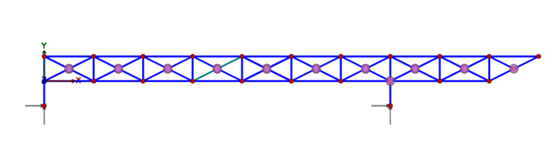 Alternative Design 2 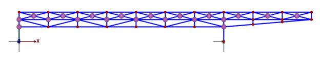 Alternative Design 3 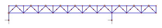 Alternative Design 4 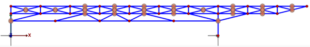 Alternative Design 5 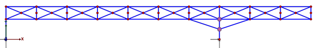 Design analysis was completed for all alternative designs. The main considerations included the number of members, number of connections, estimated weight, highest member force, and deflection. The design analysis can be seen below. 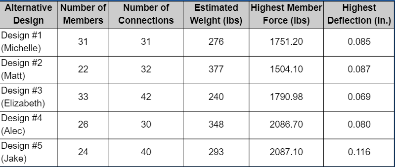
Back to Blog
Alternative Truss Designs9/29/2021 The Team met and discussed ideas for a design for the truss of the bridge. Each member created a rough sketch of a truss which are shown below. The Team will meet with their advisors to discuss the ideas. Using the envelope given by the Steel Bridge Competition Rules, designs were created based on the dimensions provided. These designs will later be modeled in Visual Analysis.
Back to Blog
Rules and Research9/9/2021 Our team has just received the rules for the 2022 ASCE/AISC Steel Bridge Competition and has begun our research into a viable design for our bridge. We began by reviewing old competitions and finding pros and cons for each design to determine how to start on our own personal designs. In the Rules, the Site Plan was laid out with dimensions required for the competition. This will determine a few of the restrictions we will have when designing our bridge. This includes skewed footings, a cantilever end, and areas where construction is restricted. 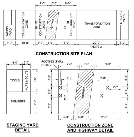 |